Find a Device’s IP Address on a Cisco Switch Port (Step-by-Step)
- Last updated: Sep 24, 2025
This guide explains how to map the IP address of a device connected to a Cisco switch port. The process is straightforward and relies on the relationship between MAC addresses, ARP entries, and physical interfaces.
The procedure involves two key steps:
- First, use the
mac address-tableto map the device’s MAC address to its physical port. - Then, check the
ARP tableto find the IP address associated with that MAC address.
Prerequisite: The switch must have an IP address configured in the same VLAN as the devices you want to identify. (This configuration is explained in the next section.)
Network Architecture
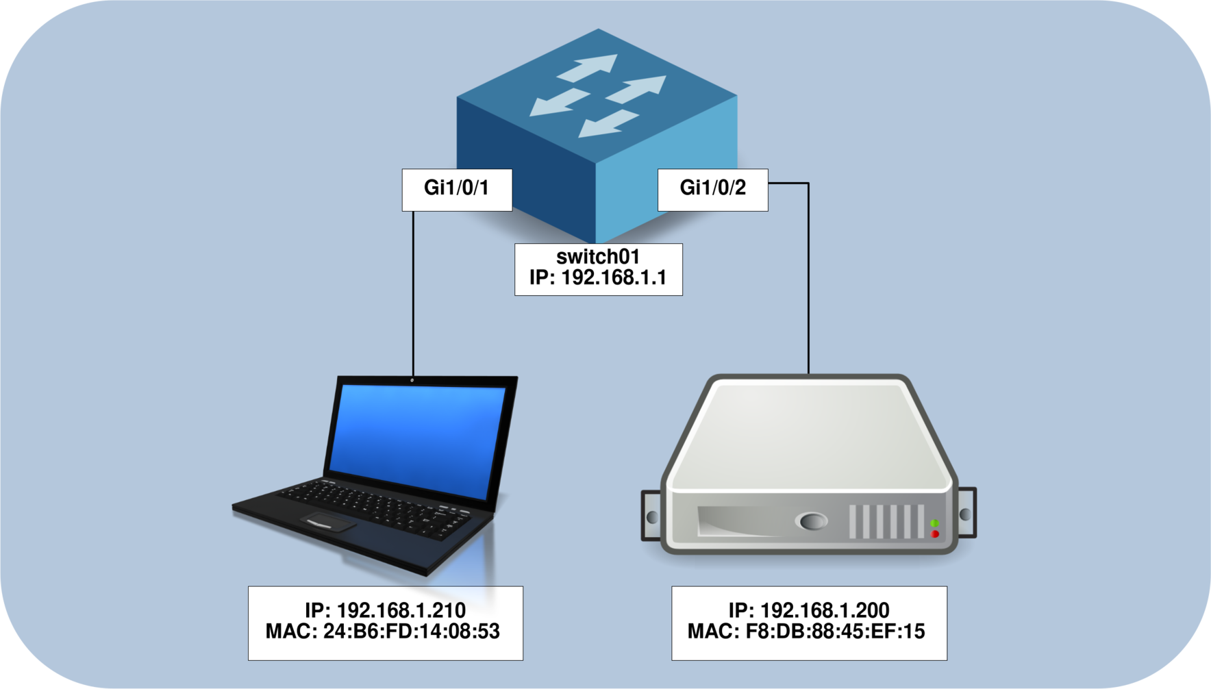
The diagram below illustrates the network setup we'll be working with. Our goal is to determine which IP addresses are associated with the devices connected to interfaces Gi1/0/1 and Gi1/0/2 on the switch.

Map IP Addresses to Physical Ports
Configure an IP Address on the Switch
- To configure the
VLAN 1interface, use the following commands:
switch01(config)# interface vlan 1
switch01(config-if)# ip address 192.168.1.1 255.255.255.0
switch01(config-if)# no shutdown
Retrieve MAC Addresses
As mentioned earlier, switches operate at Layer 2 of the OSI model, which means there is no single command to directly map an IP address to a physical port. Instead, we need to follow a two-step process:
- First, retrieve the
MAC addressesof the connected devices using the switch's MAC address table. - Then, correlate each
MAC addresswith its correspondingIP addressby consulting the ARP table.
Let’s start by identifying the MAC addresses associated with our two physical interfaces.
- Display the
MAC addressof the device connected to interfaceGi1/0/1:
switch01# show mac address-table | include Gi1/0/1
1 24b6.fd14.0853 DYNAMIC Gi1/0/1- Display the
MAC addressof the device connected to interfaceGi1/0/2:
switch01# show mac address-table | include Gi1/0/2
1 f8db.8845.ef15 DYNAMIC Gi1/0/2- Summarize the information gathered so far:
| Interface | MAC Address | IP Address |
|---|---|---|
| Gi1/0/1 | 24b6.fd14.0853 | - |
| Gi1/0/2 | f8db.8845.ef15 | - |
Retrieve the IP Addresses
- Ping the
IP addressesyou want to identify in order to populate the switch’sARP table:
switch01# ping 192.168.1.200
Type escape sequence to abort.
Sending 5, 100-byte ICMP Echos to 192.168.1.200, timeout is 2 seconds:
!!!!!
Success rate is 100 percent (5/5), round-trip min/avg/max = 36/51/74 ms
switch01# ping 192.168.1.210
Type escape sequence to abort.
Sending 5, 100-byte ICMP Echos to 192.168.1.210, timeout is 2 seconds:
!!!!!
Success rate is 100 percent (5/5), round-trip min/avg/max = 33/48/71 ms- Display the
ARP tableto correlate eachMAC addresswith its correspondingIP address. Use theincludefilter to show only the relevant entry:
switch01# show arp | include 24b6.fd14.0853
Internet  192.168.1.210              0   24b6.fd14.0853  ARPA   Vlan1
switch01# show arp | include f8db.8845.ef15
Internet 192.168.1.200 0 f8db.8845.ef15 ARPA Vlan1Based on this output, we can conclude that the device with IP address 192.168.1.210 is connected to interface Gi1/0/1, and the device with IP address 192.168.1.200 is connected to interface Gi1/0/2.
| Interface | MAC Address | IP Address |
|---|---|---|
| Gi1/0/1 | 24b6.fd14.0853 | 192.168.1.210 |
| Gi1/0/2 | f8db.8845.ef15 | 192.168.1.200 |
Map IP Addresses to Physical Ports with a DHCP Server
Having a DHCP server in the network greatly simplifies the process of mapping an IP address to a physical switch port. The DHCP service automatically maintains the association between each IP address and its corresponding MAC address, making it easier to trace devices.
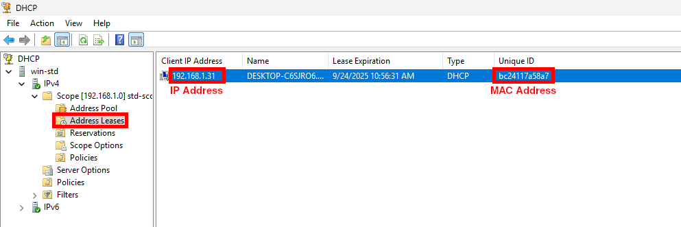
- From your DHCP server, retrieve the target IP address and the associated MAC address from the address leases list:

- Next, search for the retrieved MAC address in the switch
mac address-tableto identify the corresponding physical port:
switch01# show mac address-table | include bc:24:11:7a:58:a7
     1         bc:24:11:7a:58:a7        gi1/0/4    dynamic
The output shows the VLAN and the exact switch interface (Gi1/0/4) where the device with this MAC address is connected.