How to Harden Network Switches: Best Security Practices
- Last updated: Dec 13, 2025

While searching for a clear network switch hardening tutorial, I was surprised to find very little comprehensive information online — despite how crucial this topic is for ensuring network security. During my research, I discovered that the ANSSI 🇫🇷 💪 has published an excellent guide that I highly recommend reading: Recommendations for Securing a Service Switch. It covers more aspects than those presented in this article.
This tutorial draws inspiration from that guide to provide practical steps for hardening network switches and securing these critical devices effectively.
RADIUS configuration is not covered here, but if you wish to implement it, you can refer to my article How to Configure RADIUS Authentication on a Cisco Switch.
Update Switch Firmware
The first step in hardening a network switch is to keep its firmware up to date. The switch firmware functions much like an operating system and, over time, can develop security vulnerabilities that newer releases fix. Regularly updating to the latest firmware version provided by the manufacturer is one of the simplest and most effective ways to improve network security and stability.
If you need detailed instructions, you can follow these tutorials I wrote for upgrading firmware on Allied Telesis, HP, and Cisco switches.
Securing Switch Administrative Access
User Accounts
It’s a best practice to create a dedicated administrator account with a personal username and to disable any default or generic accounts. This adds an extra layer of security — in addition to guessing the password, an attacker would also need to know the username.
- List existing user accounts:
switch(config)# do show users accounts

   UserName    Privilege  Password        Lockout
                          Expiry date
-------------- --------- -------------- -----------
    cisco         15           -             -
Once you have reviewed the existing users, you can create a personalized administrator account and remove any default ones.
- Create a new administrator account named
johnwith privilege level 15 and a strong password:
switch(config)# username john privilege 15 password 6qu0$uck$- Then, remove the default cisco account to prevent unauthorized access using known credentials:
switch(config)# no username ciscoConsole Port
The console port is dedicated to administrative access and allows you to configure the switch through the Command Line Interface (CLI). If you need assistance connecting via this method, follow this Cisco console access guide. Since it provides full administrative control, it’s important to secure console access properly.
- Set an idle timeout on the console line to automatically close the session after 15 minutes of inactivity:
switch(config)# line console 0
switch(config-line)# exec-timeout 15
Remote Access
I personally disable both HTTP and HTTPS management access, and only enable remote administration via SSH. However, if you prefer to use a web interface, it is strongly recommended to enable HTTPS only to ensure secure encrypted access.
Telnet
- Although Telnet is rarely used nowadays, it should be disabled on legacy switches where it might still be available:
switch(config)# no telnetSSH
SSH (Secure Shell) is the recommended protocol for securely configuring your switch remotely. It encrypts management traffic, protecting login credentials and administrative commands from interception.
- Enable the SSH server on the switch:
switch(config)# ip ssh server- As with the console port, configure an idle timeout to automatically close inactive SSH sessions after 15 minutes:
switch(config)# line ssh
switch(config-line)# exec-timeout 15
Using SSH instead of Telnet ensures that all management sessions are encrypted, which is an essential step in any network switch hardening process.
Disable Unsecure Management Protocols
- Disable the HTTP server:
switch(config)# no ip http server- Disable the HTTPS (secure HTTP) server as well, if SSH is your only management method:
switch(config)# no ip http secure-serverBrute Force Protection
A brute force attack occurs when an attacker tries every possible password combination to gain access. To mitigate this type of attack, you can temporarily block authentication attempts for a defined period once a specific threshold of failed logins is reached.
- Block all authentication attempts for 5 minutes (300 seconds) if 3 failed login attempts occur within 2 minutes (120 seconds):
switch(config)# login block-for 300 attempts 3 within 120- Set a delay of 2 seconds between authentication attempts to slow down brute force attacks:
switch(config)# login delay 2Restrict Administrative Access
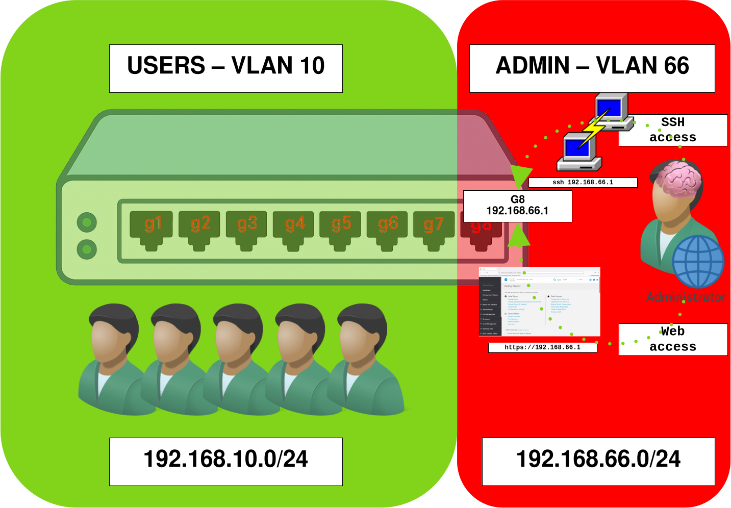
Administrative access should never be available from standard user networks. To maintain strong security, create a dedicated management VLAN and assign a specific port for accessing the SSH and/or web administration interface. You should also disable the ability for other VLANs to obtain an IP address on the switch to prevent unauthorized access from user segments.
- Create the user VLAN (
VLAN 10) and disable any IP address on its interface so that it is not used for switch management:
switch(config)# vlan database
switch(config-vlan)# vlan 10
switch(config)# interface vlan 10
switch(config-if)# no ip address
switch(config-if)# no ipv6 address
switch(config-if)# no ip address dhcp- Create the management VLAN (
VLAN 66) and assign it an IP address:
switch(config)# vlan database
switch(config-vlan)# vlan 66
switch(config)# interface vlan 66
switch(config-if)# no ip address dhcp
switch(config-if)# no ipv6 address
switch(config-if)# ip address 192.168.66.1 255.255.255.0- (Optional) You may assign a name to each created
VLAN:
switch(config-vlan)# interface vlan 10
switch(config-if)# name USERS
switch(config-vlan)# interface vlan 66
switch(config-if)# name ADMIN
The VLAN 10 is used for user traffic, while VLAN 66 is reserved for the management network dedicated to administrative access. You may also create additional VLANs — for example, one for production servers — in order to better control inter-VLAN communication through a firewall. However, this configuration is beyond the scope of this tutorial.
- Configure interface
g8in access mode and associate it withVLAN 66, so that the connected device can access the management interface192.168.66.1:
switch(config)# interface g8
switch(config-if)# switchport mode access
switch(config-if)# switchport access vlan 66- Configure interfaces
g1throughg7in access mode and associate them withVLAN 10:
switch(config)# interface range g1-7
switch(config-if-range)# switchport mode access
switch(config-if-range)# switchport access vlan 10
Securing Layer 2 and VLAN Segmentation
VLAN
Quarantine VLAN
It’s a best practice to create a dedicated quarantine VLAN and assign to it all unused ports. This way, if a device is accidentally or maliciously connected to an unused port, it won’t have access to your production network.
- Create the
VLAN 666and shut it down:
switch(config)# vlan 666 name QUARANTINE
switch(config)# interface 666
switch(config-if)# shutdown- Assign all unused interfaces to
VLAN 666and disable them:
switch(config)# interface range g3-8
switch(config-if-range)# switchport mode access
switch(config-if-range)# switchport access vlan 666
switch(config-if-range)# shutdown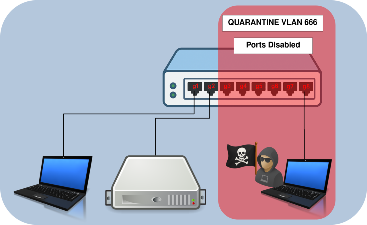
VLAN 666) used to disable unused switch ports and block unauthorized devices.Native and Default VLAN
The native VLAN is the VLAN used by the switch to exchange internal protocol information such as STP, CDP, or VTP. On a trunk link, it carries untagged frames — meaning that any untagged traffic received on a trunk interface is automatically associated with this VLAN. The default VLAN is the VLAN to which all switch ports belong until they are manually assigned to another VLAN.
By default, both of these VLANs are set to VLAN 1, which can introduce security risks. An attacker could potentially eavesdrop on or interact with sensitive protocol traffic (such as STP or CDP). Moreover, if switches in the network use different native VLANs, a technique known as VLAN hopping may occur, allowing unauthorized access between VLANs.
To reduce exposure, it’s recommended to change both the native and default VLANs from their factory settings.
Default VLAN
Disabling VLAN 1 helps prevent attackers from exploiting default configurations that are often left unchanged in many environments.
- The default VLAN (VLAN 1) should not be used for production traffic. It is recommended to disable it to reduce exposure to potential attacks:
switch(config)# interface vlan 1
switch(config-if)# shutdown
switch(config-if)# no ip address
Native VLAN
The native VLAN should be assigned to a VLAN other than VLAN 1 on every switch in the network, specifically on trunk interfaces. This helps prevent VLAN hopping and limits potential exposure of management or control traffic.
- Configure the native VLAN as
VLAN 999on the trunk interface of switch01:
switch01(config)# vlan 999 name NATIVE
switch01(config)# interface g8
switch01(config-if)# switchport trunk native vlan 999- Repeat the same configuration on switch02:
switch02(config)# vlan 999 name NATIVE
switch02(config)# interface g8
switch02(config-if)# switchport trunk native vlan 999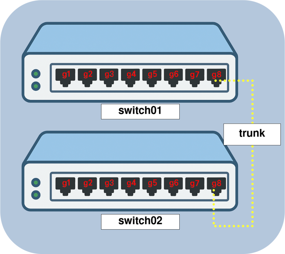
VLAN 999) on a trunk link between switch01 and switch02 to secure Layer 2 inter-switch communication.Disable Routing and Proxy ARP
Routing and inter-VLAN communication should not be handled by access switches. These tasks should be performed by dedicated Layer 3 devices such as routers or firewalls. Therefore, it is recommended to disable routing features on access switches to reduce the attack surface and ensure proper network segmentation.
- Disable Proxy ARP:
switch(config)# ip arp proxy disable- Disable IP source routing:
switch(config)# no ip source-routeDHCP Snooping and IP Source Guard
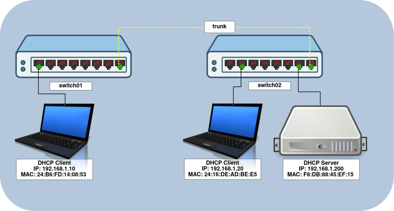
DHCP Snooping provides several layers of protection to secure the DHCP process. It allows you to define trusted ports as legitimate sources of DHCP leases, maintain a DHCP Snooping binding table within the switch’s memory to record assigned IP addresses, and limit the number of DHCP requests an interface can generate per second.
IP Source Guard uses the information stored in the DHCP Snooping table to verify that the IP address used on each port matches the legitimate DHCP binding. This feature prevents IP spoofing and helps ensure that only authorized devices can use valid IP addresses on the network.
- Enable DHCP Snooping on both switches:
switch01(config)# ip dhcp snoopingswitch02(config)# ip dhcp snooping- Specify the VLANs on which DHCP Snooping should be active:
switch01(config)# ip dhcp snooping vlan 2-4094switch02(config)# ip dhcp snooping vlan 2-4094- Define the interfaces connected to the DHCP server as trusted ports:
switch01(config)# interface g8
switch01(config-if)# ip dhcp snooping trust
switch02(config)# interface range g7,g8
switch02(config-if)# ip dhcp snooping trust- Enable the DHCP Snooping database to store binding information:
switch01(config)# ip dhcp snooping databaseswitch02(config)# ip dhcp snooping database- Enable IP Source Guard on the interfaces connected to DHCP clients:
switch01(config)# interface g1
switch01(config-if)# ip source-guard
switch02(config)# interface g2
switch02(config-if)# ip source-guard- Disable IP Source Guard on interfaces connected to devices with a static IP address (such as printers, Wi-Fi access points, etc.):
switch01(config)# interface g8
switch01(config-if)# no ip source-guard
switch02(config)# interface range g7,g8
switch02(config-if-range)# no ip source-guard- Activate IP Source Guard globally on each switch:
switch01(config)# ip source-guardswitch02(config)# ip source-guard- Verify the IP Source Guard status:
switch# show ip source-guardThis configuration ensures that each port only accepts packets with IP-to-MAC bindings verified by the DHCP Snooping table, preventing IP spoofing attempts.
Dynamic ARP Inspection (DAI)
The ARP (Address Resolution Protocol) is responsible for mapping IP addresses to MAC addresses within a local network. However, it has several weaknesses that can be exploited by techniques such as ARP spoofing and ARP poisoning. The Dynamic ARP Inspection (DAI) feature protects against these attacks by validating ARP packets against the data stored in the DHCP Snooping binding table.
By ensuring that only valid IP-to-MAC bindings are used, DAI helps prevent man-in-the-middle attacks and maintains Layer 2 network integrity.
- Trust interfaces connected to other switches or to devices with a static IP address (such as printers, Wi-Fi access points, etc.) by disabling ARP inspection on them:
switch01(config)# interface g8
switch01(config-if)# ip arp inspection trust
switch02(config)# interface range g7,g8
switch02(config-if-range)# ip arp inspection trust- Enable Dynamic ARP Inspection (DAI) on the VLANs where DHCP Snooping is active:
switch01(config)# ip arp inspection vlan 10
switch01(config)# ip arp inspection vlan 66
switch02(config)# ip arp inspection vlan 10
switch02(config)# ip arp inspection vlan 66- Validate ARP packets before allowing them through the switch:
switch01(config)# ip arp inspection validateswitch02(config)# ip arp inspection validate- Verify the ARP inspection status and statistics:
switch# show ip arp inspection statistics vlan 10
switch# show ip arp inspection
How to Protect Switch Interfaces and Improve Network Stability
Configuring Port Security on Switch Interfaces
Port Security should be implemented when RADIUS authentication is not used. It allows you to limit the number of MAC addresses that can be learned on each interface, helping to prevent unauthorized devices from connecting to the network.
- The following example shows how to enable Port Security on interfaces
g1throughg7. Each port will allow only one MAC address; if more than one device is detected, the port will automatically shut down.
switch(config)# interface range g1-7
switch(config-if)# port security mode max-addresses
switch(config-if)# port security max 1
switch(config-if)# port security discard-shutdown
switch(config-if)# port security
Securing the Spanning Tree Protocol (STP)
The Spanning Tree Protocol (STP) prevents broadcast storms by eliminating network loops. However, attackers can exploit this protocol by listening to traffic and declaring their device as the root switch, or by launching a Denial of Service (DoS) attack using fake BPDU messages to trigger frequent root elections. To mitigate these threats, you can enable BPDU Guard, which blocks any BPDU frames received on ports where this protection is activated.
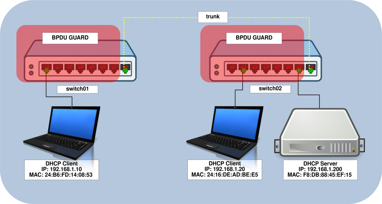
- Enable BPDU Guard on access interfaces to prevent BPDUs from being received from unauthorized devices:
switch01(config)# interface range g1-7
switch01(config-if-range)# spanning-tree bpduguard enable
switch01(config-if-range)# spanning-tree portfast
switch02(config)# interface range g1-7
switch02(config-if-range)# spanning-tree bpduguard enable
switch02(config-if-range)# spanning-tree portfast- Automatically shut down any interface that violates BPDU Guard and configure it to recover after 300 seconds:
switch01(config)# errdisable recovery cause stp-bpdu-guard
switch01(config-if-range)# errdisable recovery interval 300
switch02(config)# errdisable recovery cause stp-bpdu-guard
switch02(config-if-range)# errdisable recovery interval 300- Display the list of disabled interfaces:
switch# show errdisable interface- Manually reactivate an interface if necessary:
switch# errdisable recovery reset interface g2Configuring Storm Control
Storm Control helps keep the switch operational during excessive broadcast, multicast, or unicast traffic bursts, commonly known as network storms. By limiting the amount of such traffic, it increases the overall stability and robustness of the network.
- Use the
storm-controlcommand on all interfaces to limit traffic levels:
switch01(config)# interface range g1-7
switch01(config-if-range)# storm-control broadcast level 10
switch01(config-if-range)# storm-control multicast level 10
switch01(config-if-range)# storm-control unicast level 10
switch02(config)# interface range g1-7
switch02(config-if-range)# storm-control broadcast level 10
switch02(config-if-range)# storm-control multicast level 10
switch02(config-if-range)# storm-control unicast level 10Storm Control prevents a single malfunctioning device or broadcast flood from consuming all available bandwidth, helping to maintain network performance and availability.